


Ever made a MakerChip and wished you had a stylish render of it? Of course you have.
This one is for my fellow makers.
Today, we’re using Bambu Studio and Blender to make a render that keeps the colors and filament paths from a 3MF project. If we’re going to do this, we might as well show off the layers on the sides and the lines of filament laid across the top. We’ll start with the built-in tools, then use a dedicated add-on to round off the path ends and wall corners that stand out in close-ups. It’s all done through the interface, with a mouse and keyboard.
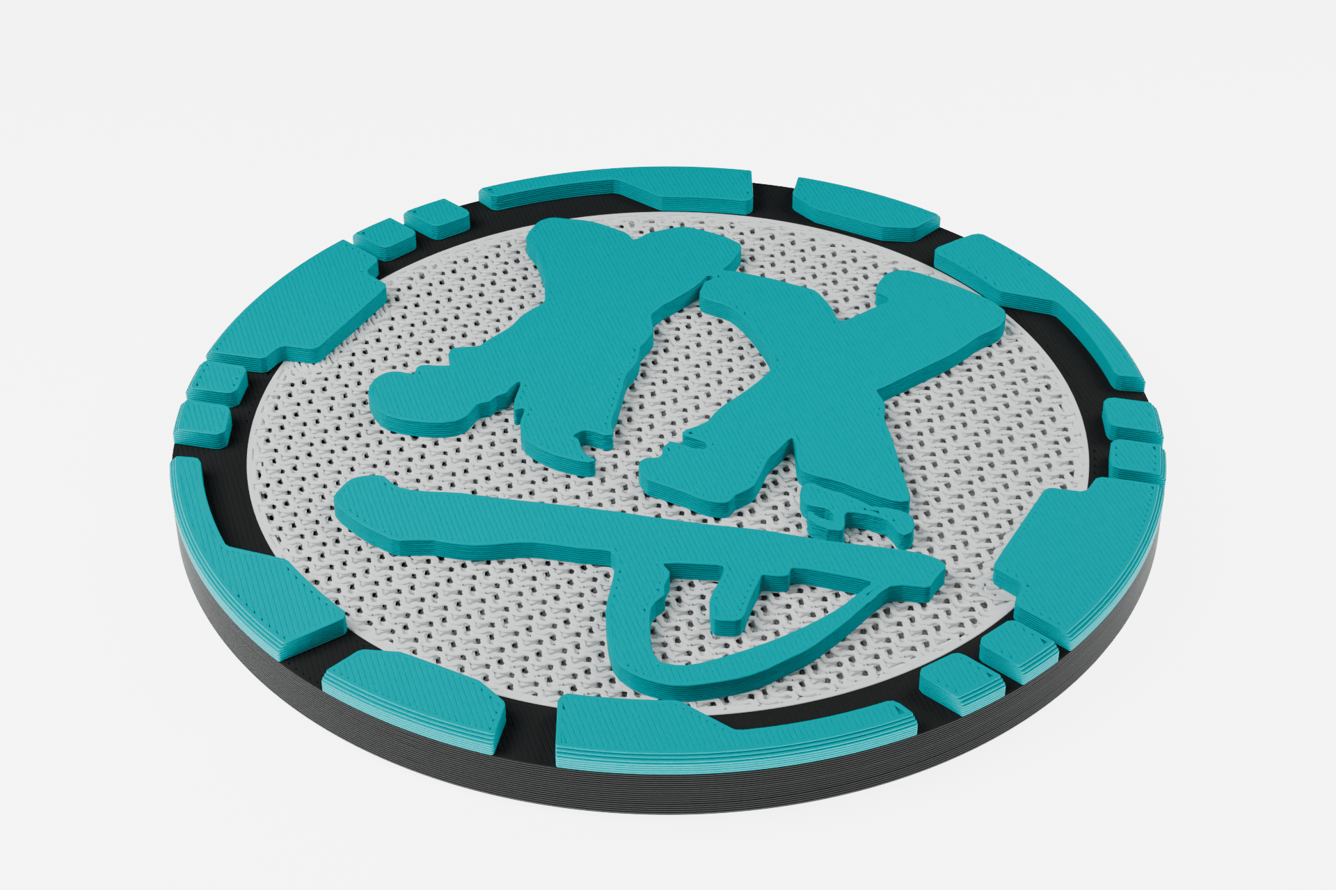
Our subject is my own Psychohead MakerChip: white, cyan, and black, 40 mm in diameter and 3 mm thick. The project, P3D JRRF2026 MC.3mf, contains 43 copies of this chip. We’ll take one of them and make a render that shows the fine filament paths from a 0.2 mm nozzle with 0.1 mm layers. If you make MakerChips, there’s a good chance your project is already a plate full of copies with the print settings dialed in. Let’s work with that very real situation.
I’m using Windows, Bambu Studio 2.8.2.61, and Blender 5.2.1. Some Bambu Studio screenshots use the Japanese interface, so I’ll give the English names of the main controls too. For Blender, we’ll use the English interface. If you need it, grab Blender from the official download page.
The finished image above uses filament geometry built from the sliced G-code, with rounded ends on open paths and rounded wall corners. First, steps 1–10 walk through rendering the standard toolpath OBJ. Then, in step 11, we’ll use the same slicing result to add those finishing touches. The paths are calculated for a 0.2 mm nozzle, so they may still look a little sharp.
The basic workflow is 3MF → Slice → Toolpath OBJ → Blender → PNG. For the rounded ends and corners, we’ll take the same slicing result through G-code → Dedicated add-on → Blender. The key to the basic workflow is Bambu Studio’s Export toolpaths as OBJ feature. A normal OBJ export gives you the surface of the original model; this option exports the sliced print paths as 3D geometry. Official Bambu Studio menu definition
1. Take one chip from a 43-chip project
Start with a copy of the original project. In File Explorer, create a working folder with three subfolders: source, toolpath, and render. Copy the original P3D JRRF2026 MC.3mf into source. (That’s my example file, of course. Use your own 3MF!)
Open that copy in Bambu Studio using File → Open Project… / ファイル → プロジェクトを開く. If you’re asked whether to load just the models or open the project, choose open the project. We need the saved filament assignments and per-part print settings as well as the geometry.
In Prepare / 準備, check that Plate 1 contains the white-and-cyan chips. There are 43 in the original file. On the left, the printer is Bambu Lab H2C 0.2 nozzle, and the process is 0.10mm Standard @BBL H2C 0.2 nozzle.

We only need one chip as the star of the render. Here’s how to isolate it. When using the shortcuts below, make sure the 3D view showing the chips has focus, rather than a text field.
- Click the chip at the lower left of the plate. I chose Assembly 46. Check it in the object list too, and select the parent assembly for the entire chip.
- Press
Ctrl + Cto copy it. - Press
Ctrl + Ato select every object on the plate, thenDeleteto remove them. - Press
Ctrl + Vto paste the copied chip. Check that the plate now contains just one chip. - Right-click the chip and choose Center / センター to place it in the middle of the plate.
- Use
Ctrl + Shift + S, or File → Save Project As…, to save it insourceasPsychohead_render.3mf.
Save under the new name before you accidentally overwrite the original. Please be careful with that one. And copy the whole chip, not just one of the tiny logo parts.
2. Check the settings and slice every layer
Before slicing, let’s check the saved settings. Leave the printer and process selections as they are, and open Layer height / 積層ピッチ to check the actual value. Don’t rely on the preset name alone. It’s probably fine, but let’s check anyway.
| Setting to check | Value for this chip |
|---|---|
| Printer | Bambu Lab H2C 0.2 nozzle |
| Nozzle diameter | 0.2 mm |
| Layer height | 0.1 mm |
| Initial layer height | 0.1 mm |
| Plate | Textured PEI Plate |
| Colors used | White #FFFFFF, cyan #00B1B7, black #000000 |
| Height and layer count after slicing | 3 mm; 30 layers |
The filament list on the left also contains gray, #545454, but the chip’s parts use only the three colors in the table. There’s no need to assign that unused color to the logo.
One detail worth explaining: this chip is made up of several separate parts, including the logo and its background. Just the white part behind the logo uses 50% Gyroid infill, 2 walls, and 0 top layers. Those are per-part overrides of the overall settings: 100% Zig-zag infill, 4 walls, and 7 top layers.
See the little holes in the white background of the finished render? With the white part set to 0 top layers, its internal Gyroid infill is exposed at the surface. It looks like a flat white shape in Prepare, but that pattern appears once it’s sliced. The overall top shell thickness is 0.8 mm, but the white part’s 0-top-layer setting takes precedence. Official Bambu Studio source: conditions for generating top shells
If your own 3MF contains multiple parts, expand the object list and check their individual print settings too. The values here are specific to this Psychohead chip. Copying the entire chip when we reduced the plate to one copy also carried over those per-part settings.
Click Slice plate / スライス at the upper right. When it finishes, check that the height is 3.00 mm and the top layer is 30. With both the initial and normal layers set to 0.1 mm, a 3 mm chip has 30 layers.
In Preview / プレビュー, set the color scheme to Filament / フィラメント. Line Type / 種類 uses colors to distinguish features such as outer walls and infill. We want to carry the finished chip’s colors into the render, so choose the filament colors here.
Set the vertical slider on the right to include everything from the first layer to the last, and move the horizontal path slider all the way to the end. Show every color you need, and check that the preview shows the completed print. The visible range and colors affect the geometry that gets exported. Bambu Studio view types; toolpath export implementation

Look for gaps or missing details around Psychohead’s outline, color boundaries, and fine patterns. You’ll also see things outside the chip, such as the tower and priming lines. We’ll export them together and remove the parts we don’t want in the image once we’re in Blender.
The original project was saved in Bambu Studio 2.6. After saving a separate copy in 2.8, the geometry, three-color part assignments, 0.2 mm nozzle, 0.1 mm layers, and per-part print overrides were checked. The application update did change some settings, including the machine start and end G-code. What we’re reproducing here is a fresh set of print paths, sliced with the conditions in the table above for use in the render.
3. Export the print paths as an OBJ
Once the preview has finished loading, choose File → Export → Export toolpaths as OBJ…. Save it in toolpath as Psychohead_toolpath.obj. This menu item appears in English even in the Japanese interface.

This export produced three files: Psychohead_toolpath.obj, Psychohead_toolpath.mtl, and tool_colors.png. The OBJ is 328,516,107 bytes (about 328.5 MB). The OBJ holds the geometry, the MTL holds the material information, and the PNG is the color palette. All those fine filament paths are actual 3D geometry, so the result is larger than the original 3MF.
Pay attention to this bit: keep all three files together in the same folder. Moving only the OBJ can break the colors when you import it. Use a separate folder when exporting another model, too. If its tool_colors.png overwrites the previous one, it can change the colors of the model you exported earlier.
Depending on the rendering backend, the export may use separate MTL materials for each color instead of a PNG. This example uses a palette image, so Blender displays multiple colors through a single material. Official Bambu Studio color palette export implementation
4. Import into Blender with the correct scale and orientation
In Blender, choose File → New → General. Move your mouse over the 3D Viewport, then press A → X → Delete to remove the default cube, camera, and light. Blender’s shortcuts act on the area under your mouse. Keep that in mind for the rest of the tutorial, too.
In the Properties editor on the right, open Scene Properties → Units and set Unit System = Metric, Unit Scale = 1.0, and Length = Millimeters. This makes dimensions easier to read in mm. We’ll set the model’s actual scale in the import options next.
Choose File → Import → Wavefront (.obj), select Psychohead_toolpath.obj, and set the import options on the right as follows.
| Option | Value |
|---|---|
| Scale | 0.001 |
| Forward Axis | Y |
| Up Axis | Z |
Scale = 0.001 converts the millimeter coordinates to Blender’s usual meter scale. Y / Z keeps the original XY plane and the print’s upward Z direction. Click Import Wavefront OBJ. Blender manual: OBJ units, axes, and material import

This data comes in as a single object, and Blender automatically loads the accompanying MTL and image. If you lose sight of it, keep it selected and use View → Frame Selected in the 3D Viewport, or press . on the numeric keypad, to bring the whole object into view. That’s the numpad period, not the regular . key.
The tower is still included, so it’s normal for the overall dimensions to exceed 40 mm at this point. Check that the thickness runs along the Z axis.
5. Remove everything except the chip
Now let’s keep just the chip. In this export, the separate tower and priming areas are part of the same object, so we’ll use X-Ray. This lets us select the vertices behind the visible surface as well.
- Select the imported object and press
Tabto enter Edit Mode. - Press
1on the top row of your keyboard to switch to vertex selection. - Press Numpad
7, or choose View → Viewpoint → Top, to look straight down. - Click the X-Ray icon (overlapping squares) at the upper right of the viewport to enable it, then choose Select → None to deselect everything.
- Press
Bfor box select. Draw a box around one complete chip and nothing else, leaving a little room around its edges. - Press
Ctrl + Ito invert the selection. Check that everything except the chip is selected, then delete it withX → Vertices. - Click the same X-Ray icon to turn it off, then press
Tabto return to Object Mode.

The X-Ray shortcut is Alt + Z, but that can conflict with the NVIDIA overlay or similar software. If it does, use the on-screen icon. Adjust the selection box to suit the layout on your own plate. If a brim touches the chip’s outer edge, check the selection carefully so you don’t remove part of the chip. If you do, Ctrl + Z will undo it.
Select the chip, press F2, and name it MakerChip. There’s no need to join anything in this example. If a different export gives you multiple objects for the colored parts, select all the objects that make up the chip and join them with Ctrl + J in Object Mode before continuing.
6. Center the origin and place the chip on the floor
Select the chip and choose Object → Apply → Rotation & Scale. Next, choose Object → Set Origin → Origin to Geometry, then immediately press F9 to open the operation panel. Set Center to Bounds Center, which uses the center of the object’s bounding box.
Using the bounding-box center instead of the average position of the vertices means we can align the bottom with the floor simply by raising the chip by half its thickness.

Press Alt + G to reset Location to 0, then check Dimensions under N → Item. After removing everything except the chip, the measured X/Y/Z dimensions in this example are 39.997995 × 39.999008 × 3.000000 mm. Blender may round these values depending on the number of digits it displays. The toolpath’s outline can differ slightly from the original model because of line width and other factors, so there’s no need to force it to exactly 40 mm.
In the same Item panel, enter 1.5 mm for Location Z. Leave X and Y at 0 mm. Raising the bounding-box center by half the chip’s thickness puts its bottom at Z=0. For another model, enter half of its Dimensions Z value.
For this Psychohead chip and the camera position we’ll use later, leave Rotation X/Y/Z all at 0°. No additional Z rotation is needed.
7. Make it look like plastic without losing the colors
Select Material Preview using the sphere icons at the upper right of the viewport. You can also select it from the Z key menu.
Switch to the Shading workspace at the top and select the chip. Check material_1 in the Shader Editor below. If the nodes are off-screen, place the mouse over the Shader Editor and choose View → Frame All to bring them into view.
In this example, Image Texture → Principled BSDF’s Base Color is connected automatically. Leave that connection in place: it’s what supplies the colors from the image. Disconnecting it and replacing it with a single color would remove the multicolor appearance.
Now change the Image Texture’s Extension from Repeat to Extend. This palette has its colors arranged in a single row, including white at the edge of the image. With Repeat and interpolation, the gray at the right edge can blend with the white at the left edge, making the white areas look grayish. Extend keeps the edge colors as they are. Leave Interpolation at Linear and Color Space at sRGB.
After changing it, check that the 3 colors—white, cyan, and the dark color representing black—match the slicer’s color assignments. You should be able to distinguish the white background, cyan logo, and dark base, with the colors carried through into the small details too.
With this standard export, the original 3MF’s black #000000 became #333333 in the palette. We’ll use that color for the standard version and match the rounded-end version to the same display color later, so they’re easier to compare. White #FFFFFF and cyan #00B1B7 retain their original values.
Change only the Principled BSDF settings as shown below. Expand the Specular heading in the node to find its setting.
| Setting | Value |
|---|---|
| Metallic | 0 |
| Roughness | 0.45 |
| IOR | 1.46 |
| Specular → IOR Level | 0.20 |
| Image Texture: Color Space / Interpolation | Keep sRGB / Linear |
| Image Texture: Extension | Extend |

Roughness controls how broadly the reflections spread. This is where your preference for gloss comes in, so try comparing values around 0.4–0.6. These are starting values for making the image, not measurements from a particular PLA. Blender manual: Principled BSDF
The layers are already modeled as geometry. Before adding Noise or Bump, see how the actual printed lines look with just the lighting.
8. Add a white floor and a camera
With the shape and colors ready, let’s add the floor and camera. Return to Layout and use Shift + S → Cursor to World Origin to reset the insertion point for new objects to the origin.
Add the floor with Shift + A → Mesh → Plane, then press F2 and name it Floor. Under N → Item, set Dimensions X and Y to 200 mm each. Leave Location X/Y/Z at 0 and Rotation at 0 too.
With the floor still selected, create a material using Material Properties (the sphere icon) → New on the right. In the Surface’s Principled BSDF, click the Base Color swatch and enter F0F0F0 in the color picker’s Hex field. Set the other values as shown in the table.
| Floor material | Value |
|---|---|
| Base Color | #F0F0F0 |
| Roughness | 0.75 |
| Specular → IOR Level | 0.10 |
| Emission → Color | White (#FFFFFF) |
| Emission → Strength | 3.0 |
Emission makes the floor look like a bright photography backdrop. If the settings are hard to find in Material Properties, you can also expand Specular and Emission in the Principled BSDF node in Shading and enter the same values there.
Next, use Shift + A → Camera. Select the new camera and enter the Location and Rotation values from the table under N → Item → Transform. You can enter positions with units, such as 40 mm. Rotation is in degrees. Matching both the position and rotation points the camera at the center of the chip.
| Camera setting | Value |
|---|---|
| Location X / Y / Z | 40 / −75 / 65 mm |
| Rotation X / Y / Z | 53.238 / 0 / 28.072° |
| Type | Perspective |
| Focal Length | 70 mm |
| Sensor Width | 36 mm |
| Clip Start / End | 1 / 2000 mm |
| Depth of Field | Disabled |
Set Focal Length and Clip under Camera Data Properties (the camera icon) → Lens on the right, and Sensor Width in the Camera panel. We’re taking a close-up of a small object, so don’t forget to set Clip Start to 1 mm.
Press Numpad 0, or choose View → Cameras → Active Camera, to switch to the camera view. Check that the whole outline is in frame and that the logo is oriented so you can read it.

9. Set up three area lights and the world lighting
Add an area light with Shift + A → Light → Area. Press F2 to name it Key, then enter its position and rotation in N → Item, just as you did for the camera. Set Power, Shape, and Size in Light Data Properties (the light bulb icon) on the right.
Repeat the process to create Rim and Fill. Key is the main light, Rim lights the outline from behind, and Fill controls how dark the shadows are.
| Area Light | Location X / Y / Z | Rotation X / Y / Z | Power | Size |
|---|---|---|---|---|
| Key | −45 / −45 / 75 mm | 40.887 / 0 / −45° | 0.070 W | 60 mm |
| Rim | 40 / 40 / 55 mm | 46.597 / 0 / 135° | 0.024 W | 40 mm |
| Fill | 40 / −55 / 90 mm | 37.540 / 0 / 36.027° | 0.014 W | 70 mm |
For all 3 lights, set Color=White, Shape=Square, Normalize=Enabled, and Spread=180°. Expand the headings in Light Data Properties and check that Normalize is enabled. With Normalize disabled, the same Power value produces different brightness depending on the light’s area. Blender manual: Light Objects
Those wattages look tiny, don’t they? That’s because the lights are very close to a 40 mm product. Entering the hundreds of watts you might use for a large scene can easily blow out the printed lines.
Next, open World Properties (the globe icon) → Surface. Set the Background’s Color to white and Strength to 0.03. This lights the whole scene and is separate from the floor material.
In Render Properties (the render settings icon), select Render Engine=Cycles and Device=CPU. Open Color Management in the same tab and set View Transform=AgX, Look=Medium High Contrast, and Exposure=0.
Switch the viewport to Rendered to check your lighting. Material Preview uses its own preview environment lighting, so judge the final brightness in Rendered mode or an actual render. If the top surface is so bright that the lines disappear, first check the wattages, units, and Normalize settings you entered.
10. Render the image and save the Blender project
We’ve made it this far. Time to turn it into an image. In Render Properties, open Sampling → Render and set Max Samples=64 and Denoise=Enabled. Leave Film → Transparent disabled so the white floor and background appear in the image.
Under Output Properties → Format on the right, set Resolution X=1920, Y=1280, and the percentage to 100%. Both the standard and rounded-end versions use this 3:2 landscape format. Setting the percentage to 50% makes test renders lighter, but remember to return it to 100% for the final image.
Press F12, or choose Render → Render Image, to start rendering. Both the standard and rounded-end versions in this article were rendered on the CPU with 64 samples. The time it takes depends on your computer, so keep an eye on the progress indicator at the bottom of the window or elsewhere in the interface.

When Render Result appears, zoom in and check for missing logo details, the printed lines on top, the layers on the sides, the color boundaries, and contact with the floor. In particular, make sure no part of the chip’s outline is cut off by the edge of the camera frame.
Once you’re happy with it, open Image → Save As… in Render Result. Save it in render as Psychohead_Native_Tutorial.png, with File Format=PNG, Color=RGB, and Color Depth=8. It’s tempting to call it done as soon as the image appears, but the PNG hasn’t been saved yet. Don’t forget this part.
Close the render window or press F11 to return to the main window, then choose File → External Data → Pack Resources. Finally, use File → Save As… to save Psychohead_Native_Tutorial.blend in render. This includes the palette image in the Blender project, making it easier to keep the colors intact when you move the file elsewhere.
11. Round off the ends and corners of the printed lines
You can already see the layers, but zoom in and the line ends and wall corners still look angular. It would be nice to make those look a little more like filament too, right?
For this finishing step, we will use the Bambu Filament Path add-on. It reads the position, width, layer height, and color of the printed lines from G-code, then turns the extruded filament into 3D geometry with rounded cross-sections. It adds flattened domes to open path ends and rounded joins at outer and inner wall corners. This is a separate process from editing the standard toolpath OBJ directly.
The end of a line and a bend in a continuous path are different places. Rounding only the ends leaves the sharp corners untouched. Here, we will finish both. The add-on builds the outline of each printed line along the original path, rather than bending the path into a shortcut around the corner.
I also tried applying Bevel to the entire OBJ, but that changed the dimensions of the line bodies and their color assignments. That is why this step uses a dedicated process. Code runs inside the add-on, but all you need to do is choose a file and use the settings panel. It uses the Python bundled with Blender, so there is no need to install Python separately or paste in any code.
Export the same sliced result as G-code
Return to Bambu Studio and open the single chip sliced in step 2. If you have closed the sliced result, open the saved Psychohead_render.3mf as a project and slice it again with the same settings.
In Preview, check that all 30 layers, totaling 3.00 mm in height, are included, then choose File → Export → Export G-code…. In the toolpath folder, save it as Psychohead.gcode. This step uses a G-code file, separate from the OBJ exported earlier.

Install the add-on
First, download the Bambu Filament Path 1.1.2 add-on ZIP. This ZIP contains the extra functionality used in the following steps.
In Blender, open Edit → Preferences → Add-ons, then choose Install from Disk from the menu at the upper right. Select the saved Bambu_Filament_Path-1.1.2.zip without extracting it, turn Enable on Install ON, and install it. Check that Bambu Filament Path is enabled in the list. If you cannot find it, enter Bambu Filament Path in the search field. Blender manual: Installing add-ons

If you already have an older version installed, save your current .blend before installing the new ZIP. After updating, quit and restart Blender, then check the version under Preferences → Add-ons → Bambu Filament Path. Meshes created with the older version will not update automatically, so import the same G-code again.
Import the finished model into the same scene
Open Psychohead_Native_Tutorial.blend, saved in the basic workflow, and switch to Object Mode. Choose File → Import → Bambu G-code — Filament Path (.gcode) and select the Psychohead.gcode file saved earlier. There are 4 import settings to check.
| Option | Setting for this example |
|---|---|
| Object Label | Leave blank. The 1 object in the file is selected automatically |
| Center XY / Ground Z | ON |
| Match Native Black | ON |
| Round Wall Corners | ON |
Round Wall Corners rounds the bends in the outer and inner walls. Leave it ON for this example. In the notes on the right, also check that the import uses high-resolution cross-sections and ends.

Click Import Filament Path to add MakerChip_Rounded. Creating this detailed geometry takes time, so give the importer a moment to finish. The completed example in this article contains 42,255,840 vertices (about 42.26 million). Generating this example used approximately 30 GB of memory. Work with 1 chip and close other memory-heavy applications to make things easier. Wait for the import to finish instead of clicking the import button repeatedly. Line width and layer height come from the G-code, so there is no need to enter 0.22 mm or 0.1 mm here.
The imported model is centered in XY, with its bottom at Z=0. Its units have already been converted from mm to Blender meters. Leave Location at 0 for X/Y/Z and Scale at 1. Its origin is set differently from the standard version, so do not repeat the move to Z=1.5 mm from step 6. There is no need to scale it by 0.001 again either.
N → Item → Dimensions lets you check that the size matches the original chip. The finished example measures approximately 39.99897 × 40.00073 × 3.00000 mm. Its cross-sections and corners are represented differently from the standard OBJ, so the X and Y bounding dimensions may not be exactly the same. There is no need to scale it to precisely the nominal 40 mm.
A material is also created for each color. With Match Native Black ON, the G-code black #000000 is displayed as #333333 to match the standard OBJ for comparison. White and cyan retain their original colors. An unused gray may remain in the material list, but the chip still uses only 3 colors.
The plastic material settings are Metallic=0, Roughness=0.45, IOR=1.46, and Specular IOR Level=0.20—the same values as in step 7. This version assigns colors through per-face materials, so it does not need the Image Texture Extend setting used for the standard OBJ.
Hide the standard version and render the finished model
Outliner: turn OFF the eye and camera icons for the original MakerChip (the standard OBJ) to exclude it from both the viewport and the render. If the camera column is hidden, open the filter at the upper right of the Outliner and enable the camera restriction toggle. You can also select the old model and check that Renders is OFF under Object Properties → Visibility → Show In. The eye icon only controls viewport visibility. Do not stop at closing the eye: check that the standard OBJ’s camera icon is OFF too. Keep the new MakerChip_Rounded visible in both the viewport and the render. If the two models overlap, you cannot properly compare the end shapes or reflections.

Keep the same floor, camera, and lights. Press F12 or choose Render → Render Image to render.
Zoom in on a bend in the perimeter wall and you can see the formerly pointed outer corner form a rounded join that follows the printed line width. Round Wall Corners applies to outer and inner walls. It does not round every infill corner, including those in the white Gyroid, with the same operation.

Each line ends in an elliptical dome joined to the flattened cross-section of the printed line. At a width of 0.22 mm, the dome extends 0.11 mm beyond the end. The line width comes from the sliced result; it is not fixed at 0.2 mm throughout. 0.2 mm is the nozzle diameter, and 0.1 mm is the normal layer height.
Compare the same path before and after rounding
The 2 images below are close-ups of printed lines generated from the same G-code, using the same camera and lighting. Look at the end of the line extending from the left: its flat cut face becomes a rounded shape that extends slightly outward. The surrounding walls and neighboring lines stay in place. Wall corners are rounded in both images, and duplicate-surface cleanup uses the same settings. This comparison isolates the addition of rounded open ends.


“Before” here means the line body generated by the add-on, before the end rounding is added. It is not a comparison with Bambu Studio’s standard OBJ; we are looking only at the difference made by the rounded ends. Some ends overlap walls and are hidden, so a close-up like this makes the change easier to see than a view of the whole chip.
Use finer geometry for close-ups
This part matters. Saving a larger image will not fix an angular silhouette if the underlying geometry is coarse. Here, the line cross-sections, end domes, and curved wall joins use finer subdivisions independently of the image size. That makes the curves clearer in close-ups, at the cost of more import time, render time, and memory.
The standard line cross-section uses 26 points, while narrow sections whose width is no greater than the layer height use 24 points. Each end dome has 11 intermediate rings. Wall-corner arcs use a resolution equivalent to a circle with 64 segments or finer. This does not mean placing 64 faces at every corner: only the portion needed for the turn angle is generated. Some locations retain the complete join to preserve the outline.
No domes are added at intermediate mesh splits, and closed paths remain closed. The original polyline is not simplified by removing points. G-code arcs are converted to short line segments with an error of 0.001 mm or less.
Where flat top or bottom surfaces overlap with the same color, height, and facing direction, only the duplicate coverage is removed. This cleanup does not move the original vertices or lift the faces slightly. It runs automatically during import.
This finish is a visual approximation built from G-code paths, not a simulation of molten plastic flowing or being compressed. Each printed line is represented as a separate shape; overlapping areas are not all fused together like plastic. The cross-sections, ends, and wall bends differ from the standard OBJ, so the appearance of the layers changes too. The exposed white Gyroid follows the original slice settings.
In Render Result, choose Image → Save As… and save to the render folder as Psychohead_Rounded_Tutorial.png. Use PNG, RGB, 8 bit, as in step 10. Back in the main Blender window, use File → Save As… to save Psychohead_Rounded_Tutorial.blend. Keeping the standard and rounded versions under separate names lets you compare the finish using the same composition.
Bambu Filament Path is an add-on I made. It is available on GitHub, so give it a try if it looks useful.
I keep making little tools for the things I wish already existed. If this one helps, I would love your support through GitHub Sponsors. Sponsors are welcome!
12. Trying the QIDI version with a 0.4 mm nozzle
If you have been wondering, “Is this just for 0.2 mm nozzles?”—I tried 0.4 mm too. This time, I used the QIDI version of my P3D MakerChip.
This project uses a QIDI Q2, a 0.4 mm nozzle, and a normal layer height of 0.2 mm. I imported the G-code generated by QIDI Studio 2.7.2.60 with Bambu Filament Path 1.1.2 and rendered it in Blender. The chip is 3 mm thick, with 15 layers. The Psychohead example earlier has 30 layers at 0.1 mm, so the difference in the sidewalls is easy to compare.

Do I need a separate add-on for a 0.4 mm nozzle?
The same add-on works here. It reads the line widths and layer heights recorded in the G-code, so there is no separate ZIP to install for each nozzle size, and no need to set every line to 0.4 mm. Nozzle diameter and the width of the deposited line are different things.
The workflow is the same as step 11: slice and export a .gcode file from QIDI Studio, then open it through File → Import → Bambu G-code — Filament Path (.gcode) in Blender. The menu still says Bambu, but it successfully read the line widths, layer heights, and colors from this QIDI Studio file. For a first attempt, a project with just one chip is the easiest place to start, as in the earlier steps.
Looking at both the logo and QR sides
This chip is designed to print with the logo facing the build plate. For Figure 17, I flipped the entire imported chip over so the logo faces up toward the camera. The QR-code side shown next is the side that faces up during printing. It is interesting to see how the filament paths differ between the two faces.


Flipping the chip also revealed a problem: overlapping faces on the underside could appear as black specks. Version 1.1.2 cleans up overlapping bottom faces as well as top faces. All three images above are actual renders made after that fix. If you have an older version, get the update from the v1.1.2 release page, restart Blender, and import the G-code again.
If you have read all this and it still sounds like a lot of work… you could always throw this article and your model at Astra and let it get on with it! Astra did all of this rendering work for me in Blender. At this point, deciding which angle to use and how you want to show the model feels more important than learning every step yourself. AI moves on while I am still trying to learn it, so I have given up trying to keep up. Now, if only tokens would get cheaper…
Troubleshooting
| Problem | What to check |
|---|---|
| Export toolpaths as OBJ is unavailable | Open Preview and wait for slicing and preview loading to finish. |
| No layer lines appear in Blender | Check that you used the toolpaths export command, rather than exporting the original model as an OBJ. |
| Colors distinguish walls and infill instead of filament colors | Set the preview color scheme to Filament before exporting. |
| The chip is entirely gray or pink | Check Material Preview. Keep the OBJ, matching MTL, and PNG together, and check the image texture connection. |
| The chip has another model’s colors | Check whether tool_colors.png was overwritten. Export each model into its own folder. |
| The white background looks gray in the standard OBJ | If the Image Texture node’s Extension is Repeat, change it to Extend. |
| Small holes appear in the white background | Check that part’s top-shell and infill settings. The white background in this example has 0 top layers and 50% Gyroid infill, so the infill is intentionally exposed. |
| The chip is enormous or extremely small | Check Import Scale and Dimensions. If 40 mm becomes 40 m, the scale is off by a factor of 1000. |
| Only some layers or part of the top surface are present | Show all layers with the vertical slider and move the horizontal path slider to the end, then export again. |
| Part of the logo or underside disappears after cleanup | Undo with Ctrl+Z, enable X-Ray, and box-select the entire chip again. |
| The render is blown out or almost black | Check the light positions in mm, Power, Normalize, World settings, and Color Management. |
| Line ends still look square up close | Show MakerChip_Rounded from step 11 and disable both viewport and render visibility for the standard MakerChip. Shade Smooth alone does not change the shape of the ends. |
| Black specks or doubled lines appear on the rounded version | First check that the standard OBJ’s camera icon is OFF. The eye icon only hides it in the viewport; the original may still render on top of the new mesh. If specks remain on the underside, update to v1.1.2 or later, which also cleans up overlapping bottom faces, restart Blender, and import the G-code again. |
| Wall corners are still sharp | Check that Round Wall Corners was ON when importing. If the mesh was made with an older version, update the add-on, restart Blender, and import the G-code again. |
| The Filament Path import command is missing | Check that Bambu Filament Path is enabled in Add-ons. If you have just updated it, save your work and restart Blender. |
| The add-on reports Multiple objects | Use the G-code from the project containing one chip. Files with multiple objects require an Object Label. |
| The rounded version floats above the floor or is too small | Import with Center XY / Ground Z enabled. Undo any extra Z translation or 0.001 scaling you applied afterward. |
Discover more from Psych0h3ad
Subscribe to get the latest posts sent to your email.

Comments